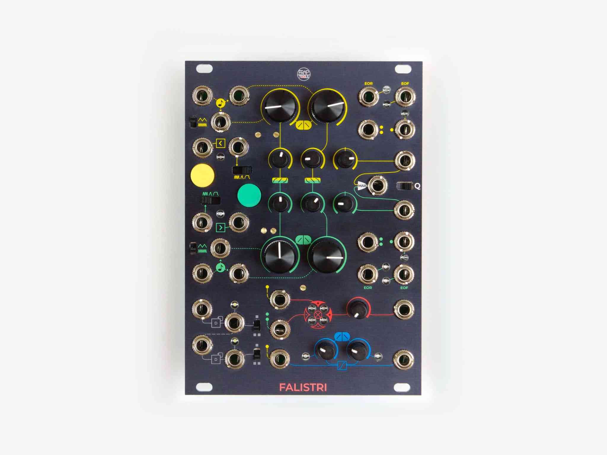
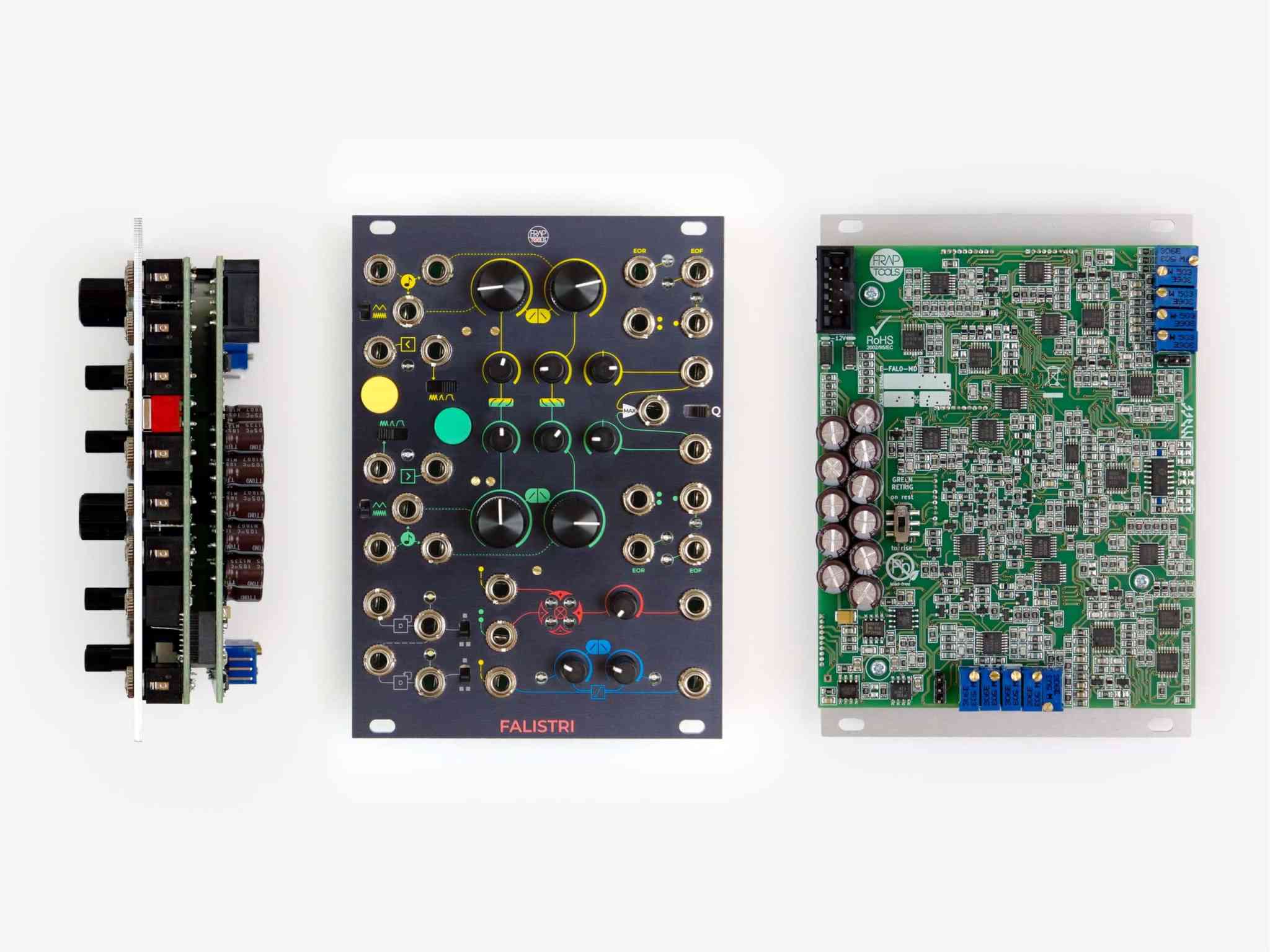
Key Features
- two generators as envelopes or oscillators
- independent shape per stage
- independent time from shape
- quadrature mode for both envelope or oscillator mode
- manual buttons for realtime performance and ease of interaction
- unipolar bipolar and attenuverted output
- EOR and EOF digital outputs
- two cascaded flip-flop for sub oscillators, clock dividers or more rhythmical combinations
- DC-coupled four quadrant multiplier usable for AM RM or as VCA
- slew limiter with separated rise and fall
- analog design
The generators are made to quickly and intuitively achieve the function needed, providing several outputs and inputs to dynamically change their times and trigs. The main peculiarity in this design is the way shapes are managed:
- times are independent from shapes – when sculpting an envelope, you can freely morph from Logarithmic to Linear to Exponential slope, without changing the time needed to complete Rise or Fall (and their Loop time when used as oscillator);
- shapes are exclusive per each stage – you can have Logarithmic Rise and Logarithmic Fall, Linear Attack and Logarithmic Fall or any other combination of the three modes, and of course any blending in between these shapes, allowing deep sculptures of sound when used as Control Voltage as well as audio source.
The time switch scales the time factor on both rise and fall stages in each generator.
Both manual button (for hands-on control) and external trigger/gate Input are available, and are used in the three possible play modes:
- Loop – where end of fall stage triggers the start of rise, incoming triggers are not needed, but if present reset the rise;
- Transient – only the low-to-high transition of the trigger/gate signal is used to start the rise stage, while fall stage is automatically recalled at the end of rise;
- Sustained – the low-to-high transition of the trigger/gate signal is used to start the rise stage, while the fall stage is trigger by the high-to-low transition of the Trigger/Gate signal.
A Gate input for switching from Loop to Transient and vice versa is also present.
Quadrature (Q) mode combines yellow and green function generators with the following stages connections:
- end of yellow rise triggers start of green rise
- end of green rise triggers start of yellow fall
- end of yellow fall triggers start of green fall
CV Outputs
- yellow and green
- unipolar 0V/+10V
- bipolar -5V/+5V
- attenuverted -10V/0/+10V
- Analog OR or Maximum function between yellow and green
Gate Outputs
- yellow and green
- End of Rise
- End of Fall

 switch to the U.K site >

